Ergonomics Software
Experience world-class MSD risk mitigation. Our powerful AI-driven SaaS global enterprise ergonomics solutions, delivering ActiveEHS® and backed by the industry’s largest team of board-certified ergonomists, improves worker health and productivity.
Watch the 4-min Quick Tour to see what goes into VelocityEHS Industrial Ergonomics.
A Total Solution Where People, Process & Workplace Intersect
A robust approach to EHS & ESG requires a comprehensive ergonomics program. Our ActiveEHS powered Industrial Ergonomics solution is the smartest way to assess and control MSD risk in the workplace.
The VelocityEHS Industrial Ergonomics Solution, part of the Accelerate® Platform, combines interactive online training, AI driven assessment tools, expert-led site improvement events, and a powerful database to deploy, monitor and manage ergonomics processes across hundreds of locations for world-class organizations like Kellogg’s, Toyota, Cummins, Lear, Northrop Grumman, General Mills, and Goodyear.
Settings
Ergonomics capabilities optimized for your specific work environment
Industrial
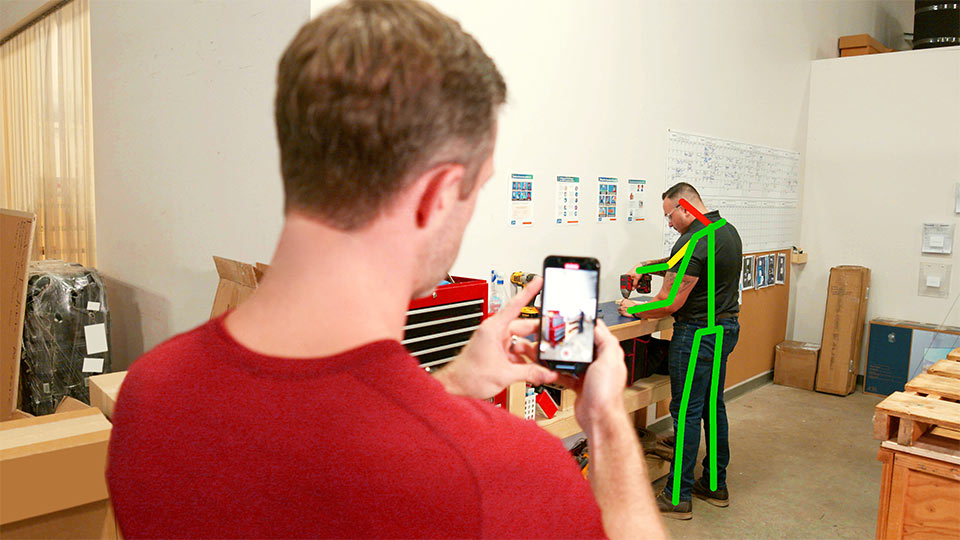
Industrial environments can seem complex, but addressing the risk of musculoskeletal disorders in them doesn’t have to be. Your industrial athletes are your most valuable resources. Don’t put them at unnecessary risk.
Office
Deploying a large-scale, multi-location office ergonomics process has never been easier. With VelocityEHS Office Ergonomics, your employees can train and assess themselves, allowing you to prioritize who needs individual attention and identify major issues and trends.
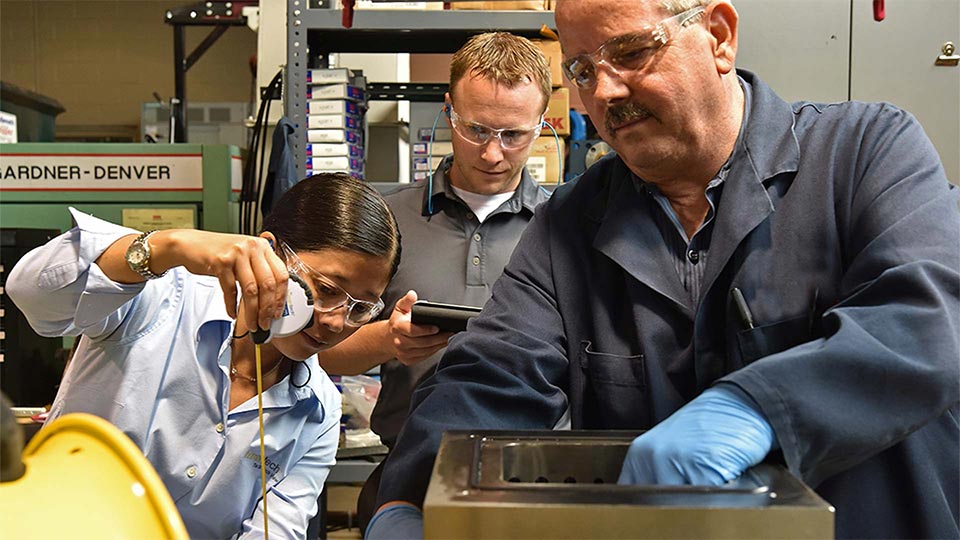
Lab
The laboratory environment poses unique challenges resulting from the use of specialized equipment. Knowing how to adjust workstations to fit the employee, and using proper work practices can improve overall comfort, accuracy, and productivity at work.
Distribution
Activities common to distribution and warehousing like lifting, pushing, and carrying can easily lead to overexertion injuries, costing companies billions. An effective, data-driven ergonomics process has a profound impact on maximizing human performance and improving the bottom line.
Field Services
When your work environment changes often, it’s hard to assess the risk of soft-tissue injuries. A consistent set of standardized tools plus the knowledge to quickly evaluate the workplace are critical. Our solutions give you a process that won’t fail, no matter where the work is.
Process
Manual material handling, high forces, tight spaces, and extreme conditions are just some of the challenges faced by workers in process industries. Proper tooling, effective ergonomics training, and good job design are a must to maintain worker health and safety.
Industries
Explore our unique Ergonomics capabilities built for any industry
Automotive
The unique aspects of the automotive industry are also the keys to success when addressing workplace ergonomics. Our approach incorporates continuous improvement with sound ergonomic design guidelines and consistent assessment methods to help you realize solid results.
Aerospace
Manual processes, long cycle times, and non-standard work can pose a challenge for addressing soft-tissue injuries in the aerospace industry. You need a flexible system that’s simple, fast, and keeps employees healthy and productive. We’ve got you covered.
Chemical
In the chemical industry, with varied work settings, the workplace improvement process must be shared by many. VelocityEHS Ergonomics makes it easy to get others involved. Our simple design engages management to end-users and drives participation.
Food & Beverage
Repetitive jobs, wet/cold environments, sanitation requirements, and a complex supply chain make the food and beverage industry ripe for MSD risk. Our simple and systematic tools engage employees and gain the attention of management to drive steady and continuous improvement.
Manufacturing
No matter which assembly or manufacturing process you use, your workers are still your most valuable investment. Keep your industrial athletes from the risks of developing soft tissue injuries with a consistent and sustainable ergonomics process.
Pharmaceutical
Diverse work environments and heavy regulations make the pharmaceutical industry one of the more difficult in which to introduce workplace changes. Our ergonomic design guidelines and process-driven approach will help you get it right the first time and prevent injuries before they happen.
Tools to Enhance Your Ergonomics Process
3D SSPP
Our 3D Static Strength Prediction Program™ (3D SSPP) software predicts static strength requirements for material handling tasks, so you can evaluate the physical demands of a job and reduce the risk of injuries.
ROI Calculators
Building the business case for ergonomics is the key to getting your program and job improvements funded. Speak in terms your leadership will understand with these estimators, developed by our in-house board-certified professional ergonomists.
Program Self-Assessment
Easily gauge the current state of your ergonomics program to find gaps and strengths and ensure your process is moving in the right direction. Get personalized results and custom recommendations for actionable next steps.
The Accelerate Platform is
EHS & ESG done right.®
Insightful
Business intelligence & reporting
Helpful
Built-in guides & training
Friendly
3rd party Integration ready
Fast ROI
Accelerated time-to-value
Simple
All actions & tasks in one place
Informative
Auto alerts, emails & texts
Multilingual
20+ languages
Effortless
Easy to update & upgrade
Attentive
Committed customer support
Secure
GDPR & SOC 2 compliant
Have questions about the VelocityEHS Accelerate® Platform?
Learn from the best
We’re invested in your continued education and success. Check out the latest industry news, our most recent blogs, and helpful training resources that will ensure you stay ahead of the curve.

California’s ESG Disclosure Rules: What You Need to Know
ESG
California is now the first US state with ESG disclosure requirements. Here are some major takeaways about California’s ESG disclosure rules.

The Ergonomics Hit List®: A Simple Tool to Identify Issues in the Workplace
Ergonomics
In industrial environments, it’s important to take the time to properly assess the workplace for musculoskeletal disorder (MSDs) risks which can lead to sprains, st…

The Importance of Control of Work on the Path to Maturity
Control of Work
Managing contractors, temporary workers and visitors, making sure they’ve completed the necessary training, and ensuring they have the proper credentials and permit…
Partner with the most trusted name in the industry
Stress less and achieve more with VelocityEHS at your side. Our products and services are among the most recognized by industry associations and professionals for overall excellence and ease of use.